Lenovo IP Controller - Deployment Guide
Lenovo IP Controller - Deployment Guide
Lenovo IP Controller - Deployment Guide
Description
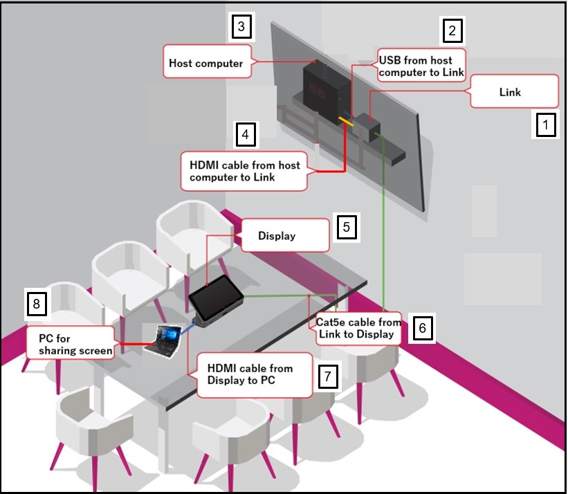
Describes the point-to-point installation for the Lenovo IP Controller as shown below.
Applicable Devices
Solution
Overview, Requirements, and Installation Concept
The Lenovo IP Controller includes the following components:
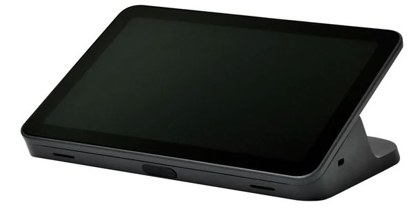
- Touch Display
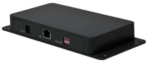
- Link
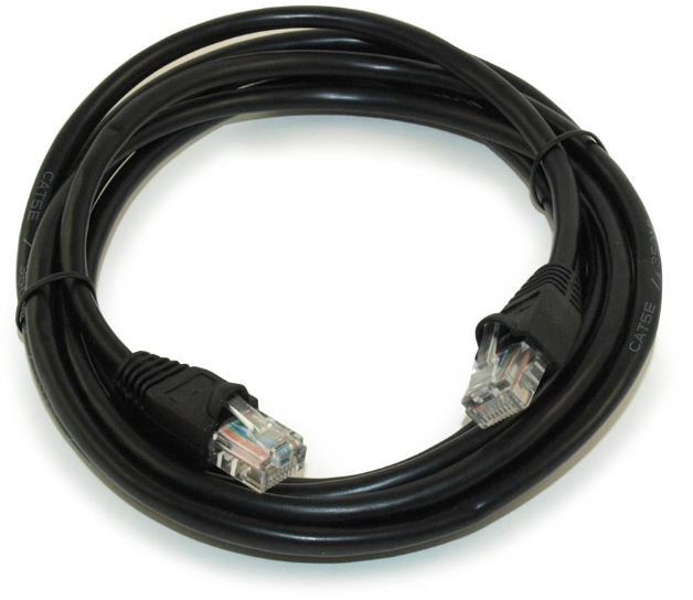
- 5-meter (16.4-feet) CAT5e RJ45 Ethernet cable
- 2-meter (6.4 feet) HDMI Cable
- 1-meter (3.2 feet) HDMI Cable
- 1-meter (3.2-feet) USB 3.0 Type-B to USB-A cable
- AC Power Adapter
The installation requires one CAT5e cable to be installed, point-to-point between two devices: Touch Display and Link. The Touch Display and Link are not on the same network. No other wired network devices may share the cabling.
The maximum distance between the Touch Display and Link is 100 meters (328 feet) using a dedicated CAT5e cable.
| Component | Description | Notes |
| 1 | Link | |
| 2 | USB from host computer to Link | |
| 3 | Host computer (ThinkSmart One, ThinkSmart Core) | Typically installed behind a large screen in a conference room. |
| 4 | HDMI cable from host computer (ThinkSmart One, ThinkSmart Core) to Link | |
| 5 | Touch Display | Typically placed on the conference room table. |
| 6 | CAT5e cable from Link to Touch Display | Green wire represents the CAT5e cable between the Touch Display and Link.
|
| 7 | HDMI cable from Touch Display to PC | |
| 8 | PC for sharing screen |
Link Setup
Follow these steps to install the Link:
- Place the Link near the host computer (ThinkSmart One, ThinkSmart Core). Ensure that the host computer is connected to the internet.
- Connect the 1-meter (3.2 feet) USB 3.0 Type-B to USB-A cable:
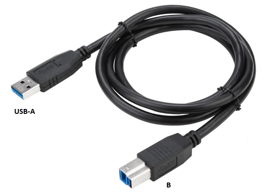
- Type-B side to the Link USB-Host port
- USB-A side to the host device (ThinkSmart One, ThinkSmart Core) USB-A port
- Connect the CAT5e cable to the To Display (RJ45) port.
- Connect the 2-meter (6.4-feet) HDMI cable
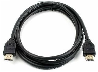
- To the Link HDMI Out port
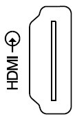
- To the host device HDMI-in port. A HDMI-in port is designated by
- The Channel ID switches can be ignored and do not have any function.
- Connect the AC Power adapter.
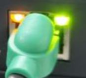
- If the green light on the RJ45 connector is On, the Touch Display and Link are connected.
Touch Display Setup
Follow these steps to install the Touch Display:
- Place the Touch Display on a conference room table, or any location with easy accessibility.
- Connect the CAT5e cable to the Ethernet From Link (RJ45) port.
- The Channel ID switches can be ignored and do not have any function.
- If planned, connect the HDMI cable to the HDMI Capture port to a PC system HDMI port.
- The Touch Display does not require a separate AC Power Adapter. Power is supplied by CAT5e Power-over-Ethernet (POE) cable.
- If the green light on the RJ45 connector is On, the Touch Display and Link are connected.
- The Touch Display display power-on is approximately 15 seconds after the Link is connected to a host device. If after 60 seconds, the display is not active, disconnect and reconnect the CAT5e RJ45 cable. This is only required during the initial installation.
Related Articles
Was this information helpful?
Your feedback helps to improve the overall experience
Document ID:HT515207
Original Publish Date:04/18/2023
Last Modified Date:02/20/2025

